DESIGN OF SEWER SYSTEM
INTRODUCTION
Design of Sewer System. Sewer system plays a vital role in the economic development of a country. Sewers are must for the drainage of waste water. In order to have an effective sewage system the sewers should be properly designed and more care should be taken in finding the invert levels otherwise whole design may get wrong. Design of Sewer System. Sewers are designed for the drainage of waste water coming from houses, industries, streets, runoff etc to protect the environment and people from serious diseases, as more than 50 diseases spread from sewage. So for a good living, the sewers should be properly designed and the sewage should be treated properly before discharging it into the river. Design of Sewer System
Some of the important and relevant terms for sewer system are discussed below….
Sewage
It is Liquid Waste or Waste Water produce as a result of water use.Design of Sewer System
Sewer
It is the pipe or conduit for carrying sewage. It is generally closed and flow takes place undr gravity (Atmospheric Pressure). Design of Sewer System
Sewerage
Sewerage is the system of collection of waste water and conveying it to a point of final disposal with or without treatment. Design of Sewer System
Sources of waste water
Following are the principal sources of waste water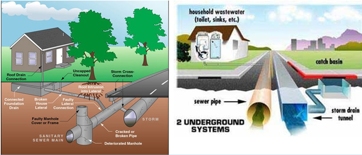
- Domestic
- Industrial
- Storm water
Domestic
It is the waste water from houses, offices, other buildings, hotels and institutions. Design of Sewer System
Industrial
It is the liquid waste from the industrial places from their different industrial processes like dying, paper matting, tanneries, chemical industries, etc. Design of Sewer System
Storm Water
It includes surface runoff generated from rainfall and the street wash. Design of Sewer System
Types of Sewer Systems
Following are the types of sewerage. Design of Sewer System
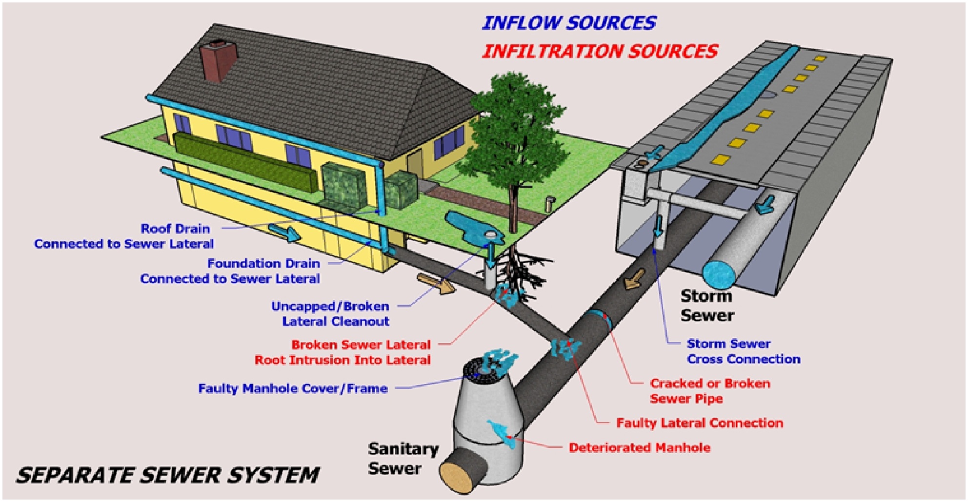
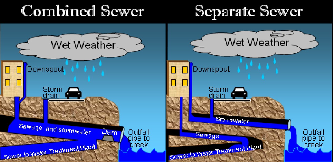
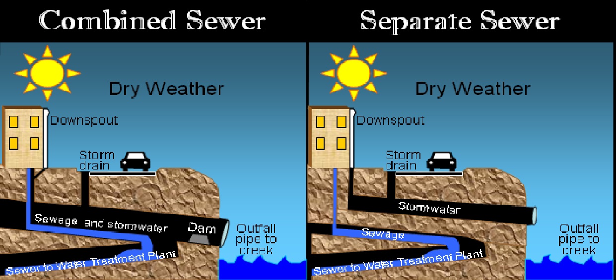
Separate System
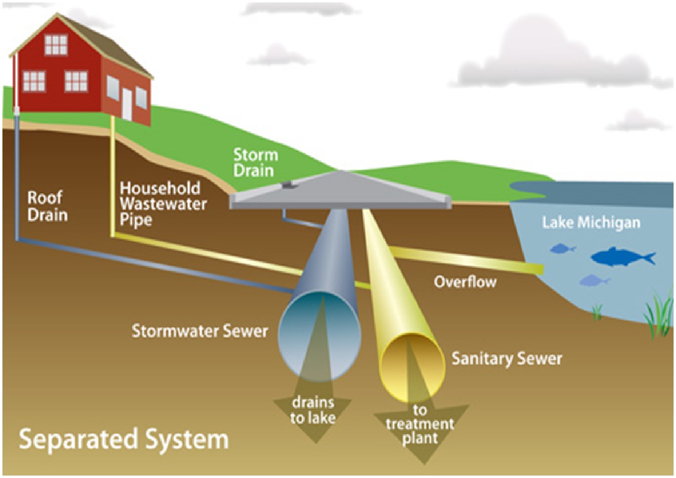
It is the system in which storm water is carried separately from domestic and industrial waste water. This system is preferred when
- There is an immediate need for collection of sanitary sewage but not for storm water
- When sanitary sewage needs treatment but the storm water does not. Design of Sewer System
Combined System
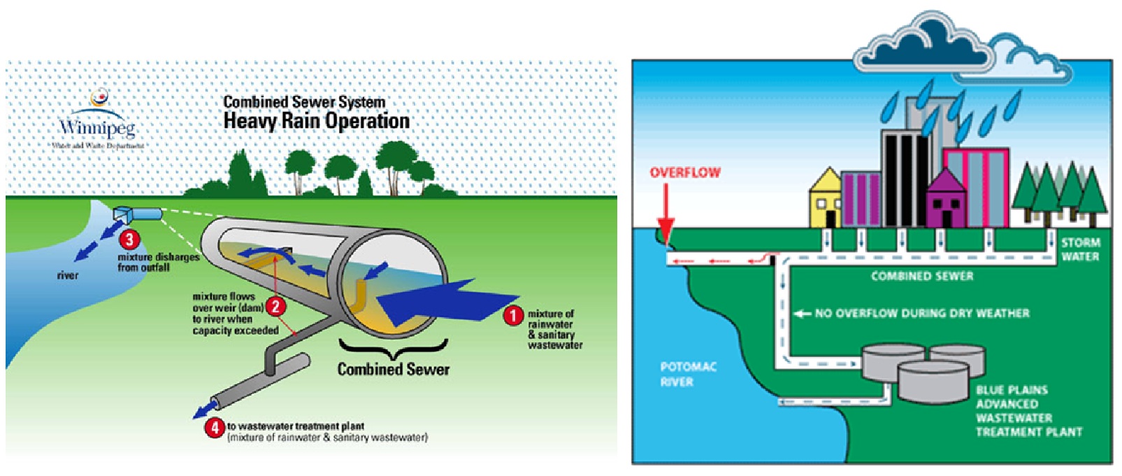
It is the type of system in which sewer carries both the sanitary and storm water. Combined system is favored when
- Combined sewage can be disposed off without treatment
- Both sanitary and storm water need treatment
- Streets are narrow and two separate sewers can not be laid. Design of Sewer System
Types of Sewers Design of Sewer System

Sanitary Sewers
It carries sanitary sewage i.e. waste water from municipality including Domestic and Industrial wastewaters. Design of Sewer System

Storm Sewer
It carries storm sewage including Surface Runoff and Street Wash. Design of Sewer System

Combined Sewer
It carries domestic, industrial and storm sewage. Design of Sewer System
House Sewer
It is the sewer conveying sewage from plumbing system of building to common/municipal sewers.
Lateral sewer
This sewer carries discharge from two or more house sewers. Design of Sewer System
Sub-Main Sewer
This sewer carries discharge from two or more laterals. Design of Sewer System
Main/ Trunk Sewer
It receives discharge from two or more sub-mains.
Outfall Sewer
It receives discharge from all collecting system and conveys it to the point of final disposal.


Sewage flow
It is flow derived from the sanitary and industrial sewage that is the raw water from these industries and houses, so it means it has direct relation with the amount of water consumed.
Generally 80 to 90 % of the water consumption is taken as sewage or waste water flow. Design of Sewer System
Variation in sewage flow
Like water supply, sewage flow varies from time to time. Since sewers must be able to accommodate Maximum Rate of Flow, the variation in the sewage flow must be studied.
Generally Herman Formula is used to estimate the ratio of Maximum to Average Flow

P is population in thousands. Design of Sewer System
WASA Lahore Design Considers the following relationship for sewer design
| Average Sewage Flow (m3 /day) | Peak Factor |
| ≤ 2500 | 4.0 |
| 2500 – 5000 | 3.4 |
| 5000 – 10000 | 3.1 |
| 10000 – 25000 | 2.7 |
| 25000 – 50000 | 2.5 |
| 50000 – 100000 | 2.3 |
| 100000 – 250000 | 2.15 |
| 250000 – 500000 | 2.08 |
| > 500000 | 2.0 |
Infiltration
It is amount of water that enters into the sewers through poor joints, cracked pipes, walls and covers of manholes. Design of Sewer System
- It is nonexistent during dry weather but increases during rainy season.
- Water and Sanitation Agency (WASA) Lahore uses the following infiltration rates for the design of sewer system.
| Sewer Diameter | Infiltration |
| 225 mm to 600 mm | 5 % of Avg. Sewage Flow |
| > 600 mm | 10 % of Avg. Sewage Flow |
Design Period
Sewer System
Period of design is indefinite. The system is designed to take care for the maximum development of the area. But we take design period of 20 years for our sewer system. Design of Sewer System
Sewer Pumping Station
- Design period is 10-years.
- Rate of Flow are average daily, peak and minimum flow including Infiltration.
PROJECT DESCRIPTION
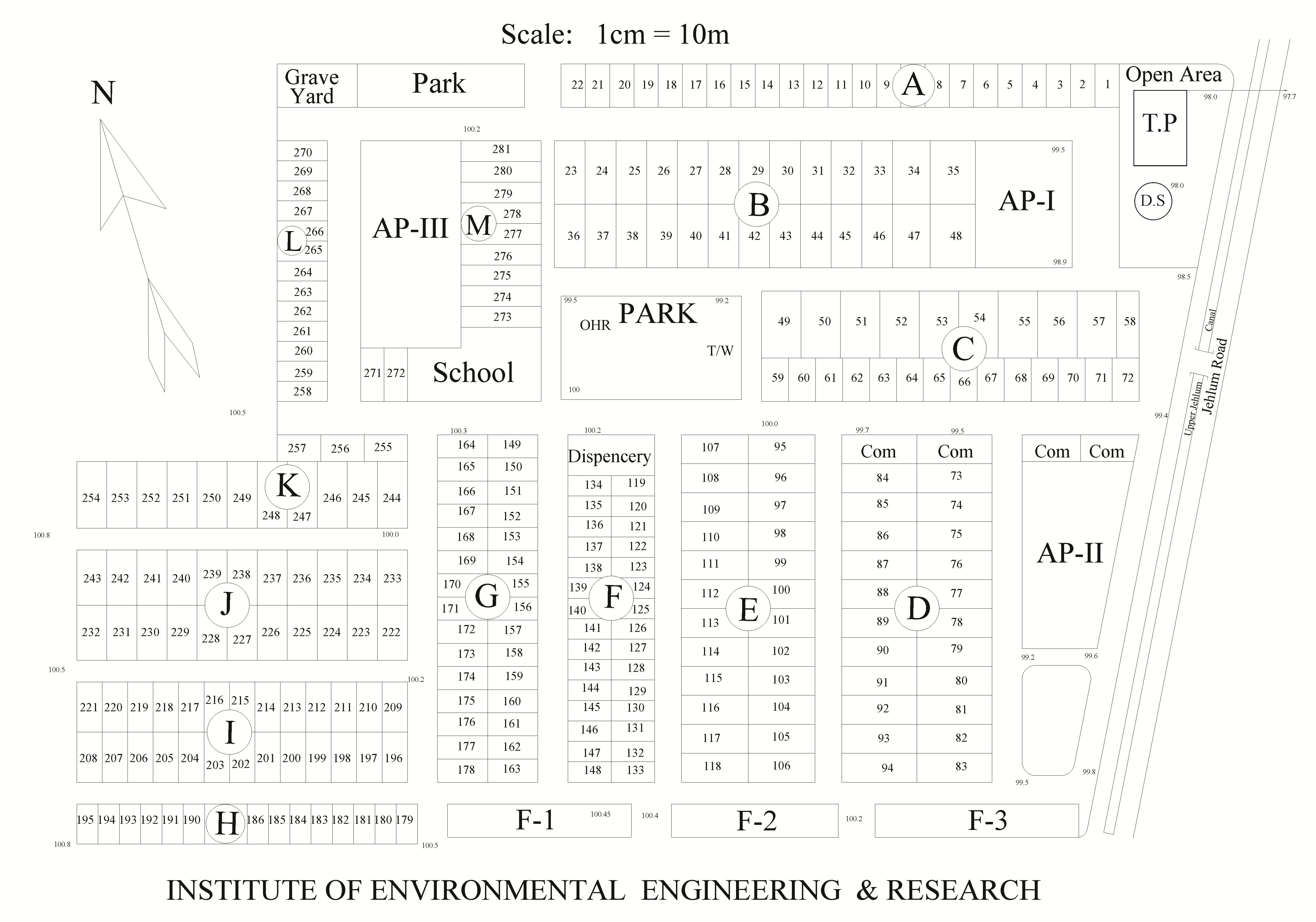
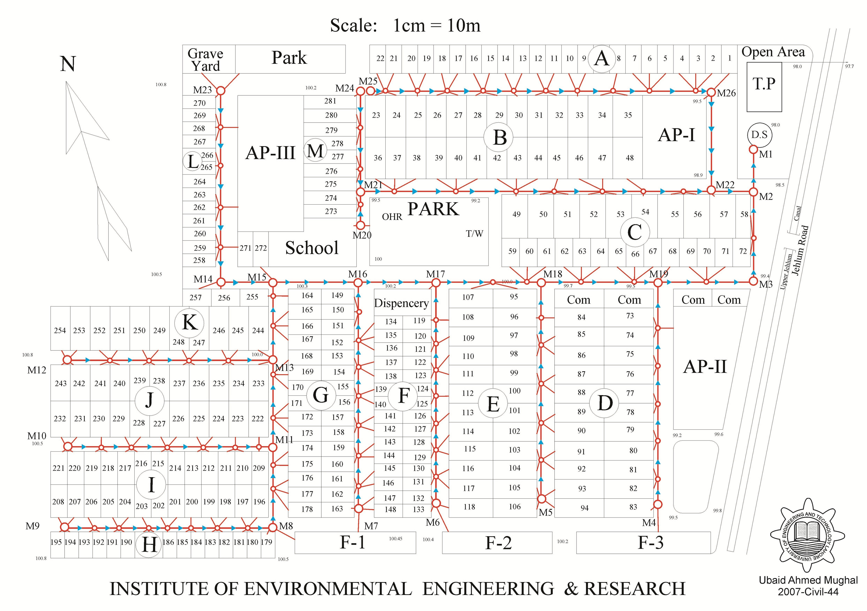
The project is based on the design of Partially combined sewerage system of a community which is having approximately a flat terrain because the difference in the reduce levels is very small. I have designed the sewage pumping station along with the hydraulic statement and the required drawings plus some extra drawings. I am confident that my design will work successfully and there will be not any problems. The Layout of the community is given as under. Design of Sewer System
DESIGN CRITERIA
Design Flow
First of all calculate the average sewage flow on the basis of water consumption and the population at the end of the design period. i.e at the full development of the area. Then the design flow for sanitary sewer and partially combined sewers can by calculated by using the following formulae. Design of Sewer System
- For Sanitary Sewer
Qdesign= Peak sewage flow + infiltration
- For partially combined sewer (WASA Criteria)
Qdesign = 2xPeak sewage flow + infiltration
Design Equation
Manning’s Equation is used for sewers flowing under gravity Design of Sewer System

Where
V = Velocity of flow in m/sec
R = Hydraulic mean depth (A/P) = D/4 when pipe is flowing full or half full
S = Slope of the sewer
n = Coefficient of roughness for pipes
Minimum (Self Cleansing) Velocity
Sewage should flow at all times with sufficient velocity to prevent the settlement of solid matter in the sewer. Self Cleansing Velocity is the minimum velocity that ensures non settlement of suspended matter in the sewer. Design of Sewer System
The following minimum velocities are generally employed
- Sanitary sewer = 0.6 m/sec
- Storm sewer = 1.0 m/sec
- Partially combined sewer = 0.7 m/sec
Maximum velocity
The maximum velocities in the sewer pipes should not exceed more than 2.4 m/sec. This max velocity in the sewer should not exceed this limit of 2.4 m/sec. It is to avoid the excessive sewer abrasion and also to avoid steep slopes. Design of Sewer System
Minimum Sewer Size
225mm is taken as the minimum sewer size. The reason being that, the choking does not take place even with the bigger size particles, which are usually thrown into the sewer through manholes. Design of Sewer System
Minimum Cover of Sewer
1m is taken as the minimum cover over the sewers to avoid damage from live loads coming on the sewer. Design of Sewer System
Spacing of Manhole (WASA, Criteria)
For (Sewer Size) 225mm to 380mm spacing not more than 100m
For (Sewer Size) 460mm to 760mm spacing not more than 120m
For (Sewer Size) greater than 760mm spacing not more than 150m
Direction of Sewer Line
Sewer should flow, as for as possible the Natural Slope. Design of Sewer System
Design of Sewer
- Size of Sewer
Use the following relation to find the diameter of sewer
Qf = A x V
- Slope of Sewer
Select the minimum velocity value and use the Manning’s formula
![]()
Invert Level
The lowest inside level at any cross-section of a sewer pipe is known as Invert Level at that Cross-section. Design of Sewer System
Invert Level = NGSL/Road Level – Depth of Sewer – Thickness of Sewer – Dia. of Sewer

Joints in Sewers
- Bell & Spigot Joint
- Tongue &Groove Joint
Manholes
These are provided for
- Cleaning
- inspection and
- house connection
At
- Change in Sewer direction
- Change in sewer diameter
- Change in slope
One man hole to be provided for 2-4 plots Design of Sewer System
Design of Sewer System
SEWERAGE DESIGN DATA
No of Plots = 281
No of Apartments = 3
No of Flats = 3
Design period = 20 years
POPULATION FORECAST
| Present (2009) | Design (2029) | |
| Persons/plot | 7 | 10 |
| Persons/apartment | 400 | 600 |
| Persons/flat | 200 | 400 |
POPULATION FORECASTING
Present Population Pp= 1) 281×7+400×3+200×3 = 3767
Design Population Pd= 2) 281×10+600×3+400×3 = 5810
Annual Growth Rate = 2.1% (For Pakistan, 2008 report)
Design Population Pd
Design of Sewer System
1) Pd = Pp x (1+2.1/100)20
Pd = 3767x(1+2.1/100)20 = 5709
Pd = 5810 ( From Table)
Per capita water consumption = 350 + 44= 394 lpcd (liters per capita per day)
Average Design flow = Pd x water consumption x 0.8 / 1000
(80% goes to sewers as waste water)
= (394 x 5810 x 0.8 ) / 1000
Qavg = 1831.312 m3/day
Peak factor = 4 (from WASA table)
To Check Infiltration rates


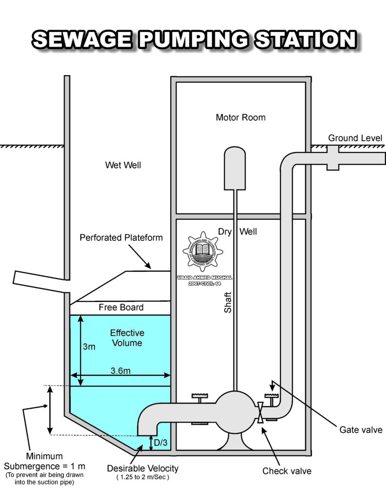
DESIGN OF WET WELL
Qmax = 14742.1m3/day = 10.237 m3/min
Pumping capacity
P = Qmax = 10.237 m3/min
Minimum cycle time Design of Sewer System
Minimum Cycle time must not be less than 5-minutes
For smaller pumps t min = 15 min
Volume = V = [P x t(min)]/4
Effective Volume = ( 10.237 x 15 ) / 4 = 38.39 m3 Design of Sewer System
DIMENSIONS OF WET WELL
Length = 3.6 m Design of Sewer System
Width = 3.6m
Height = 3 m
Volume = 3.6*3.6*3 = 38.88m3
Pump must run for at least 2 minutes
Check the cycle time , should be greater than 2 minutes
t = V/(P-Qmin) = 38.39 / (10.237 – 0.6358) = 3.99~=4
So 4 minutes is greater than 2 minutes ..( OK) Design of Sewer System
Cycle Time for Minimum and Average Flow
CYCLE TIME = t = (V/(P-Q))+(V/Q)
For Qmin = 38.39 / (10.237 – 0.6358) + 38.398/0.6358 = 64.391 min > 15min (OK)
For Qavg = 38.39 / (10.237 -1.271) + 38.39/1.271 = 34.48 min > 15min (OK)


MANHOLE

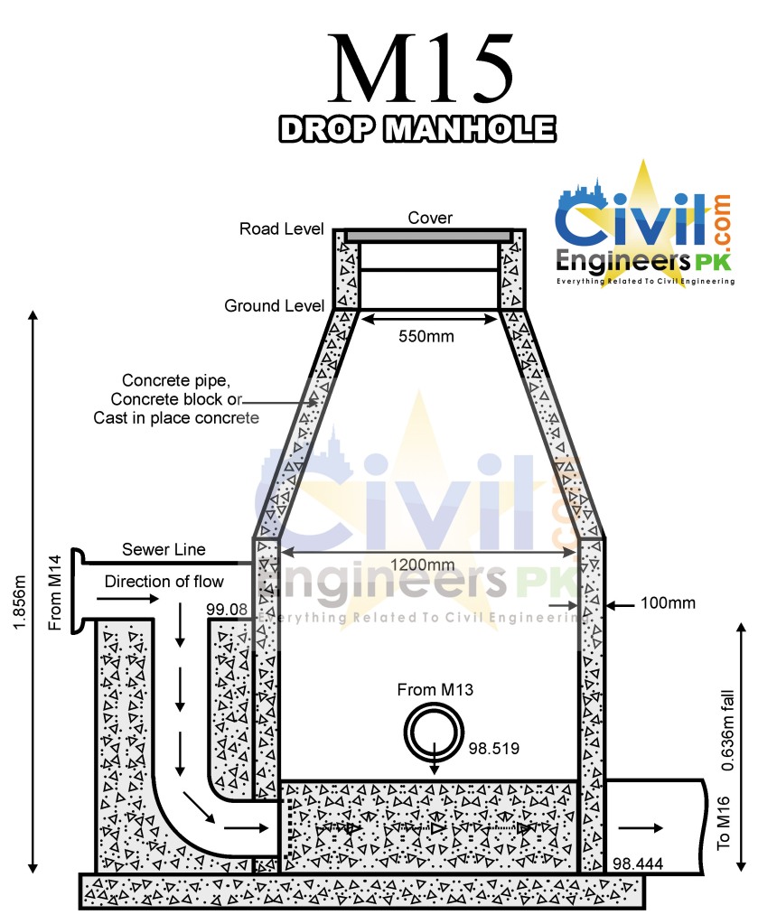
DROP MANHOLE
 SEWER JOINTS
 SEWER JOINTS
SEWER BEDDINGS

COMMENTS
- This design is based on partially combined sewerage system thus is economic.
- All the necessary things are taken from the WASA tables and Minimum velocity is taken as 0.6 m/sec which is the self cleansing velocity and velocity must not be more than 2.4 m/sec.
- Minimum diameter of sewer is taken as 225 mm and other diameters are rounded to the locally available in the market according to WASA standards.
- Minimum rate of sewage flow is taken as 50% of average sewage flow.
- Minimum clear cover of 1-m is provided above the sewer in order to avoid from impact of live loading.
- Flush tanks are provided where velocity is less than 0.6 m/Sec. Design of Sewer System
RESULTS
- Diameters are less then 600mm so Infiltration rate used is 5% of average sewage flow.
- Bell & Spigot joints have been used as the diameters are less then 600mm.
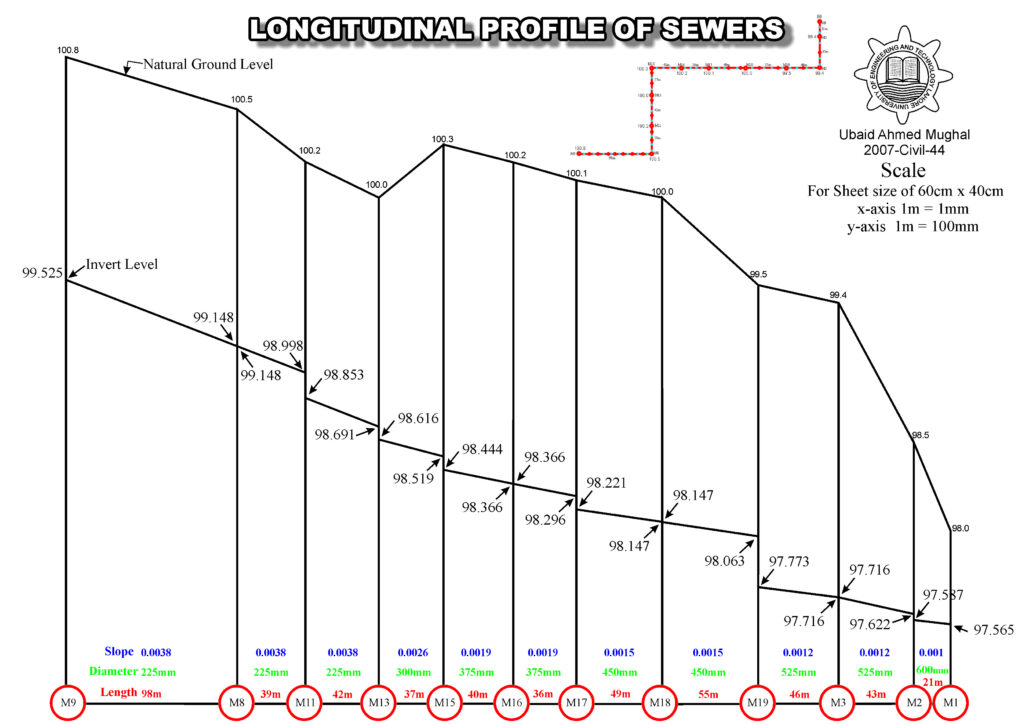
- One Drop Manhole is coming at M15 as the vertical drop is more than 0.6m.
- In Sewers (M9-M8, M8-M11, M10-M11, M12-M13, M5-M18, M20-M21, M24-M21, M21-M22, M25-M26), Velocity is less than the self cleansing velocity So, Flush tanks will be provided here.
- Most of the diameters are of 225mm ensuring the economic side of the project.
- Wet well dimensions are 2.5×3.5×4.4.
- Cycle time of 15 minutes is satisfied ensuring the adaptability of small pumps so more economic.
RECOMMENDATIONS
- Flush tanks should be flushed once in 24 hours to avoid sediment deposition.
- If the sewer is to be laid under the water table then crushed stone bedding should be used.
- Sewers should be joined in a manhole keeping the crowns at the same level.
Design of Sewer System, Design of Sewer System, Design of Sewer System, Design of Sewer System, Design of Sewer System, Design of Sewer System, Design of Sewer System
Design of Sewer System, Design of Sewer System, Design of Sewer System, Design of Sewer System
Good Work Sir
I am working as Sub Engineer at a TMA. I got enough guidance from work good work.
Regards
THANKS
You said that the drainage design is equal to two times the maximum discharge while when calculated leakage reported that drainage design is equal to two times the rate of discharge .. I hope statement this point if allowed
It best description for sewar design & it’s so halpfull for me. So thank u sir
You are Welcome
This informatiion is help me alot in designing of the sewer system , thanks soo much
Welcome
Very good material, it will be more beneficial if you could have shown the calculation or uploaded supporting excel file.
NOPE
You said that the drainage design is equal to two times the maximum discharge while when calculated leakage reported that drainage design is equal to two times the rate of discharge .. I hope statement this point if allowed
HI:
I WOULD LIKE TO BUY PROGRAM FOR DESIGN SEWAGE NET WORK WITH PROFILE.
All softwares available on the site require membership.
http://civilengineerspk.com/membership/
I cannot download Excel sheets as I require one for the design of Sewerage system though I got the membership
All excel sheets are available here only
http://civilengineerspk.com/excel-sheets/
Would like to inquire more on how to overcome excess sewage in places where there is already established sewer line yet there is increased population
How much sewage you are talking about ? 😛
I WOULD LIKE TO BUY PROGRAM FOR DESIGN SEWAGE NET WORK WITH PROFILE
its already available free online
Thanx alot. This article was a lifesaver. I am doing something similar for my undergrad project. Is there information on ABR (Anaerobi Baffle Reactor) sizing and formulas?
Thanx again.
your welcome 🙂
Hello sir your work is very appreciable, sir can you plz tell me how many types of networking are there in sewerage system and what are their names. And also where does the peak facor like 4.5,4,3 come from.
Hope u would consider my question.
Thank you!
http://civilengineerspk.com/design-of-sewer-system/
Please send Excel sheet for the design of sewerage system on my ID litafat@gmail.com Please note that I got the membership, thanks
All excel sheets are available here http://civilengineerspk.com/excel-sheets/
I would like to ask if I want to design separate sewer system where is the different will be is it in the slopes only!!, and what type of pipe you recommend UPVC or GRP
You will be using all parameters of separate sewer system like discharge, self cleansing velocity etc.
could you please give me an example of the Analysis statement for main sewer for any area?
what ?
Impressive ..can u plz tell me what should be the covering thickness for Rcc pipes Binith the main road if pipe size is approximately 24 inch in dia
This was really helpful, i m working on my college project and this kinda helped me save time to go through all the literature regarding design as m already running short of it. Thank you!
You’re Welcome 🙂 We are glad that it helped you.
Hello,
I am a student at the University of Wisconsin – Stevens Point. For a interpretive media class I have to design a sign for a local waste water treatment plant in Green Bay to use to educate their visitors. I am looking for an image of a separate sewer system to use in the sign and came across a couple on your website that would be perfect. I was wondering if you would allow me to use any of your images and if you have any high quality versions of them?
You can click on them and download them as per your requirement.
The site was worth visiting for me. it was indeed which helped me the most in doing my final year project in Diploma course this year. so i would like to thank and say i am very pleased to get accessed to this. thanks for the helps.
You are Welcome 🙂
can u do it piiz
No we dont solve questions here
here design of sewer in software tool was missing sir like autocad or staad pro ect if u provide that it will help for up coming civil engg student like me
Thanks Sir ap k iss design ki wajah se hamin khud zyada type nai krna para 😛 😀
Samajh Aani chahiye ta k khud kar sako.
what is the minimum threshold for opting separate sewerage system in terms of Indian conditions?
You can ask here https://www.facebook.com/groups/jobsforcivilengineers/?ref=bookmarks
Thankyou very much. I just found the solution to all my civil engineering problems.
Welcome
GOOD GUIDELINES TO UNDERSTAND THE BASICS OF DESIGN
Thanks
great. keep it up
Thanks
wow,it is very attractive design.I like it so much.go ahead
wow that is better design i like it go ahead
Thanks
What a perfect lesson. I really appreciate the efforts and time you have spent preparing this.
Thankyou
sir plz tell me how we design the combined sewer
Its written in this article. If you want us to design it, feel free to contact civilengineerspk@gmail.com
How far from a residential house should a main sanitary sewer manhole be? I’m talking about the one that usually goes in the middle of the street.
One was covered up when my house was being built last year and it’s only 15 feet from my front door in my front yard. It’s also a major T- junction for the neighborhood. The metropolitan sewer district said the developer idefinitely put it in the wrong place and it should have been in the street or in the sidewalk. I just don’t know what the codes are for Kentucky.
Thanks Dave
http://www.nicholasville.org/planning/GeneralSpecifications_2013.pdf
Download this file
how i can cite it?
Give reference of this site
We take Sewerage system design project in final year in UET Peshawar Bannu campus..We use your pattern to design the sewer..plz mention the softweres u used in layout of sewer..
Really appreciate your work…
EPA.NET 2.
Thanks
A.o.A
i am student of MSc in water resources engineering in uet lahore. i am working on rehabilitation of combined sewer for which i require existing design of any colony or town in lahore.
my email id is
chahmadraza413@gmail.com
you can use this
how to find slope
Formula
How to design separate sewer system kindly guide me
Follow the procedure by using values of separate design
Assalam u Alaikum!
Sir, I was your student in UET (2015-2019).
I can’t getting from where you get the values of Qmax = 10.237 m3/min , Qmin = 0.6358 m3/min and Qavg = 1.271 m3/min in design of wet well.
Kindly help me.
Dont remember now. Its very old
Will you please check it out from your sheets?
Will see
AOA, i can’t understand that how we calculated “d” and “Va” that’s in excel sheet
May be from hydraulic statement. I dont remember now its very old.
Per capita water consumption = 350 + 44= 394 lpcd (liters per capita per day).
sir what is 350 and 44….
its too old.
I have bookmarked this webpage since 2018 and it comes in handy every single time. Thank you for your efforts.
Welcome
Sir how to calculate the water consumption. Pl elaborate
Available in WASA codes